

The First Affiliated Hospital of Zhengzhou University was founded in September 1928. In 1958, it moved to Zhengzhou from Kaifeng and renamed as the First Affiliated Hospital of Henan Medical College. In 1985, it was renamed the First Affiliated Hospital of Henan Medical University. In 2000, it was incorporated into the new Zhengzhou University and officially named as the First Affiliated Hospital of Zhengzhou University.
The First Affiliated Hospital of Zhengzhou University is one of the few modern comprehensive hospitals in China, which integrates teaching, scientific research, medical treatment, prevention, health care and rehabilitation, and has strong treatment ability, international communication ability and high scientific research level. With a target of 10,000 beds and an annual outpatient volume of about 4 million, it is known as the “Central Plains Medical Aircraft Carrier” and can be called the largest hospital in the world.

Due to the increasing of large-scale hospital equipment, new buildings often have fire hazards due to adjustments to departments, changes to original design uses, and power overload.
In addition, the hospital has a large flow of people, centralized equipment, pressure vessels, chemical reagents, bedding and paper and other inflammable and explosive materials, dense buildings, connected channels, and the majority of vulnerable groups (patients). Once a fire occurs, it may cause significant property losses and casualties.
Aware of these, the First Affiliated Hospital of Zhengzhou University has constructed the SCK600 electrical fire monitoring system: in the comprehensive outpatient building, outpatient building, medical technology building, emergency building, inpatient building A, inpatient building B, inpatient building C, administrative research and teaching building, as well as the important circuit distribution boxes in the basement, the electrical fire monitoring detectors sck600y and sck600yt are installed in the distribution boxes of each important circuit in the basement The leakage current and temperature parameters of each circuit are transmitted to the electrical fire monitoring unit sck630, and the monitoring unit then transmits the data to the host sck680-b in the fire control room. Relevant management personnel can realize centralized control and centralized management on monitoring unit and monitoring host.
When the relevant parameters in the circuit are abnormal, the monitoring equipment will send out sound and light alarm to indicate the alarm position. At the same time, the on-site detector will send out light alarm and control signal to remind the management personnel to check or replace the hidden circuit, so as to reduce the risk of fire caused by electrical reasons.
The project uses 5 sets of SCK680-B1008 electrical fire wall-mounted monitoring host, 136 sets of SCK630 electrical fire monitoring units, 1117 sets of SCK600Y electrical fire residual current monitoring detectors, 1117 sets of SCK600YT electrical fire temperature monitoring detectors and 1117 sets of NTC temperature sensors.
SCK600 electrical fire monitoring system adopts a three-layer distributed design of equipment layer, communication layer and management layer to realize distributed control and centralized management.
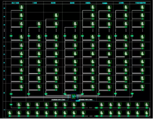
A SCK600Y residual current monitoring detector and a SCK600YT temperature measuring monitoring detector are installed on each circuit that need to be tested, to monitor the residual current and temperature value of each circuit in real time, and transmit the data to the SCK630 monitoring unit and SCK680-B1008 host through the two bus, and display the detailed circuit name, number and various function buttons on the main interface.
According to the different specifications of the cables and the rated current of the circuit, different specifications and models of SCK600Y electrical fire residual current monitoring detector should be selected. The specific specifications and dimensions are as follows:
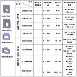
SCK600YT temperature measuring type electrical fire monitoring detector is connected with electrical fire monitoring equipment or monitoring unit through the fire-fighting second bus to realize the alarm and fault timely reporting; with the NTC temperature sensor, it can measure 4-channel temperature signals in real time, and the temperature measurement range is -10~150 ℃, high-bright LED lamp indicates the operating status of the detector, TH-35-7.5 standard rail installation.
Install a monitoring unit SCK630 every 25 detectors in the 8 buildings of comprehensive outpatient building, outpatient building, medical technology building, emergency building, inpatient building A, inpatient building B, inpatient building C, administrative scientific research and teaching building and the basement. It is used for on-site monitoring of small areas.

SCK630 electrical fire monitoring unit comes with 1-way down-line fire-fighting second bus; it can downward monitor the real-time data and alarm signals of up to 32 SCK600Y electrical fire monitoring detectors; it has sound and light alarm function and displays alarm position, Chinese prompt to help users determine the alarm position faster and more accurately; it can record more than 10,000 alarm event records, support the functions of silencing, self-check and reset; which can be rewritten on-site by monitoring equipment or buttons, and engineering debugging is simple and reliable.
- Optional 1 RS485 communication, which can be connected to related acquisition equipment for networking of large-scale electrical fire monitoring systems;
- At the same time, 1 channel of leakage and 4 channels of real-time temperature monitoring are available;
- Communicate with the monitoring equipment through the fire-fighting second bus to realize the alarm and timely report;
- It can be used as an isolator and can improve the communication distance of the bus.

SCK680-B1008 wall-mounted host is installed in the fire control room for centralized control and management of the whole project.
Working power supply: main power supply: AC220V 50Hz (allowed to change within 85% ~ 110%); backup power supply: when the main power supply is under low voltage or power failure, the working time of the monitoring equipment is ≥ 4h.
Communication mode: Fire two bus mode: pulse 24 V non-polarity two bus, special communication protocol to realize alarm interrupt report, transmission distance ≤ 1.5km. RS485 bus mode: Modbus RTU communication protocol, half-duplex mode, transmission distance 1.2km (the communication transmission distance can be extended by repeater).
Monitoring alarm: The monitoring equipment receives the monitoring alarm signal from the detector in real time, and sends out sound and light alarm signals within 30 s, indicates the alarm position, records the alarm time and keeps it until manual reset. The alarm sound signal can be manually eliminated, and it can be restarted when the alarm signal is input again.
Fault alarm: In case of communication failure between monitoring equipment and detector, under voltage of main power supply and backup power supply failure, the monitoring equipment indicates fault information, sends out fault prompt tone and lights up fault led indicator.

Users can realize the following functions on the host:
Real-time monitoring
The system monitors the residual current and temperature values of each circuit in real-time, and displays the detailed circuit name, number and various function buttons in the main interface.
Alarm setting and prompt
The system supports remote setting of residual current, temperature alarm values and various circuit information and status. When an alarm occurs in the circuit, the system will send out sound and light alarm signals, at the same time, the interface will send out obvious color changes, and automatically record events in a detailed sequence. The number of event records is more than 60,000, which is convenient for tracing.
Alarm and fault record
The system is equipped with a special historical database that provides historical alarm records and historical fault records. Users can access, query and print at any time through the report interface. Users with higher authority can delete records one by one or all.
Alarm printing
The monitoring equipment is equipped with a micro printer, which can print alarm and fault information automatically/manually. It supports automatic printing information when alarm/fault occurs through setting interface.
Historical data trend curve
For the residual current and temperature data that was stored in history, the system supports the curve query, the query time interval and dynamic setting circuit. The interface can reflect the real-time change of residual current or temperature in any time period.
Status information display
The system can display various current status information (power supply status, equipment fault status, alarm status and current working status of all communication equipment, etc.) in real time and keep synchronous display with the indicator light of monitoring equipment.
System fault self-check
The monitoring equipment can display the operation status of various internal functional modules in real time and has the function of fault self-diagnosis. At the same time, it can display the fault reason in real time on the system interface, and judge the communication status of the detectors in each area in real time, and carry out intelligent self-check for the fault of the whole system.
User level management
The system is divided into three levels of authority management, different operations need the corresponding authority level to operate, in order to prevent misoperation and illegal access.
System operation information
The system has independent information window, which records all the operation information of the equipment after starting operation, which is convenient for comprehensive judgment of the current state of the operating system.