

Grounding for Safety
Provision of adequate grounding in a substation and switching stations is very important for the safety of operating personnel, as electrical devices do not exceed tolerable thresholds and grounding is resistant to dissipate the ground fault.
What does a good electrical substation and switching station ground really mean?
The importance of an effective, durable, and reliable ground to ensure safety from electrical hazards requires no further detail.
When grounding, connecting electrical equipment to the general ground, it has a very low resistance.
1. Requirements for Good Substation Earthing
The object of a substation grounding system is to provide below and around the substation a surface that should have as uniform potential and as nearly zero or absolute ground potential as possible.
The main requirements of a good grounding system in a substation are:
i. Stabilizes circuit potentials with respect to ground and limits overall potential rise.
ii. Protect life and property from overvoltage.
iii. Provides a low impedance path to fault currents to ensure fast and consistent operation of protective devices during ground faults.
iv. Keeps the maximum voltage gradient across the surface in and around the substation within safe limits during ground faults.
2. Maximum Permissible Resistance of the Earthing System
| Large power station | 0.5 ohms |
| Major sub-station | 1.0 ohms |
| Small sub-station | 2.0 ohms |
| In all other cases | 8.0 ohms |
| The earth continuity inside an installation | 1.0 ohms |
3. Touch Voltage (E-TOUCH)
The potential difference between a ground metallic structure and a point on the earth’s surface separated by a distance equal to the normal maximum horizontal reach of a person, approximately one meter as shown in figure 1

4. Step Voltage (E STEP)
The potential difference between two points on the earth’s surface separated by a distance of one step that will be assumed to be one meter in the direction of the maximum potential gradient as shown in the figure.
5. Earthing System in a Substation
The grounding system consists of the grounding (or) grid, grounding electrodes, grounding conductors and grounding connections.
5.1 Ground Mat or Grid
The main requirement of grounding is to have a very low ground resistance. If you measure the individual electrodes driven into the ground, it will have a fairly high resistance.
But if the area of these individual electrodes is interconnected within the ground, it increases the area in constant with the ground and creates a number of parallel paths and thus the value of the ground resistance in the interconnected state, which is called the combined earth resistance; it will be much lower than individual resistance.
Therefore, if a ground electrode is driven into the ground, the interconnection can be made by a small link between that electrode and the nearby ground mat.
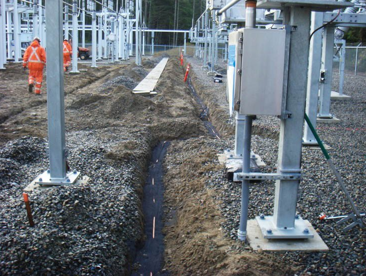
5.2 Construction of the Ground Mat
The substation site, including the fence, is separated at intervals, for example, four meters wide in length and width. Along these lines trenches are dug from one meter to 1.5 meters deep and one meter wide. Sufficiently sized ground conductors (depending on the fault current) are laid at the bottom of these trenches. All crosses and joints are braced.
The trenches are then filled with soil of a uniform fine mass of soil mixed with the required chemicals depending on the resistivity of the soil. If the equipment location is fixed, the intervals are also set so that the ground mat passes close to the equipment location to facilitate interconnection.
Typically, the earth mat is buried horizontally at a depth of about half a meter below the soil surface and the earth rods at suitable points.

Figure 3 – Substation grounding
5.3 Earth Mat in a Substation
Earth Mat is connected to the following in a substation:
1. The neutral point of said system through its own independent ground.
2. Equipment frame and other non-current-carrying parts of substation electrical equipment.
3. All foreign wireframe work not associated with equipment.
4. Operating pipe handle.
5. Fence if you are 2m from the dirt mat
6. Location of the Ground Electrode
The location of the ground electrode should be chosen in one of the following types of soil in the order of preference:
1. Wet swampy soil.
2. Clayey, clayey and arable soil
3. Clay and marl mixed with different proportions of sand, gravel and stones.
4. Damp wet sand, peat.
Dry sand, gravel, limestone, granite, very stony soil, and all places where virgin rock is very close to the surface should be avoided.
6.1 Pipe Electrode
It must be made of G.I class “B” tubing. The internal diameter should not be less than 38mm and it should be 100mm for the cast iron pipe. The length of the pipe electrode should not be less than 2.5 m. It should be embedded vertically.
Where hard rock is encountered, it can lean vertically. The slope should not be more than 30 from the vertical.
The distance between two electrodes in such a case will preferably be not less than twice the length of the electrode as shown in Figure 5.

Figure 5 – Pipe Electrode
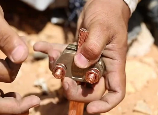
7. Grounding of Various Equipment in the Substation
7.1 Isolators and switches
A flexible ground conductor is provided between the handle and the grounding conductor attached to the mounting bracket and the switch handle is connected to the grounding mat via two separate connections made with flat MS.
One connection is made to the closest longitudinal conductor, while the other is made to the closest transverse conductor on the mat.
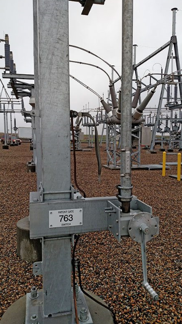
Figure 6 – HV switch grounding
7.2 Lightning Rod
Conductors as short and straight as possible to ensure minimum impedance should connect the bases of the arresters directly to the earth grid. In addition, there should be as direct a connection as possible from the ground side of the lightning rod to the frame of the equipment being protected.
In the case of lighting arresters mounted near transformers, the grounding conductor should be located away from the tank and coolers to avoid possible oil leaks caused by electrical arcs.

7.3 Circuit Breakers
For each switch there will be five ground connections to the ground plate with: Flat MS (i) switch body (ii) relay panel (iii) switch TC (iv) Two sides of the switch frame.
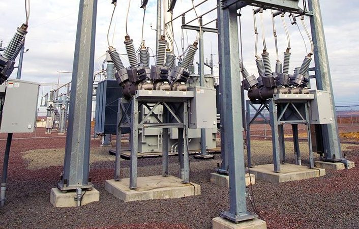
Figure 8 – Circuit breakers grounding (photo credit: Casteel Corporation)
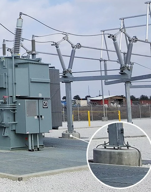
7.4 Transformers
The tank of each transformer must be connected directly to the main network. Also, there should be as direct a connection as possible from the tank to the ground side of the outgoing lightning rods.
The neutral bushing must be grounded via two separate strips to the ground grid and, likewise, must be free to classify the cell and coolers.

Figure 9 – Transformer structure grounding
7.5 Current Transformers and Potential Transformers
The supporting structures of the base unit of the Current Transformer and Potential Transformer, all bolted cover plates to which the bushings are attached, are connected to the ground mat by means of two separate connections made with flat MS.
One connection is made to the closest longitudinal conductor, while the other is made to the closest transverse conductor on the mat.

Figure 10 – High Voltage Substation (circuit breakers, instrument transformers)
7.6 Other Equipment
All switchgear and isolator equipment, structures, and metal frames must be grounded separately as shown in figure 11.
7.7 Hurdles
The substation fence must generally be too far from the substation equipment and must be grounded separately from the station ground. The station and the land of the fence must not be linked.
If the distance between the fence and the station structures cannot be increased by at least five feet and if the fence is too close to the substation equipment structure, etc., the station fence must be connected to the ground of the station. close.
“Otherwise, a person touching the fence and the station ground simultaneously would be subject to very high potential under fault conditions”.
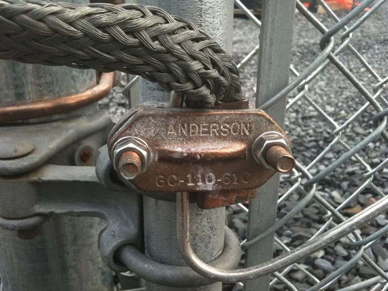
Figure 12 – Substation fence earthing
In a fence very close to the station area, a high shock voltage can be avoided by ensuring good contact between the fence stations and grounding the fence at intervals. The station fence must not be connected to the station ground, but must be grounded separately.
However, if the fence is close to the metal parts of the substation, it must be connected to the station ground.
7.8 Ground Wire
All ground cables from a station must be connected to the station ground network.
In order for station ground potentials during fault conditions not to be applied to transmission line ground cables and towers, all ground cables arriving at the station must be broken and insulated on the supply side. The station of the first tower or pole outside the station by means of 10 disc insulator.
7.9 Cables and Brackets
Metal jacketed cables within the station ground network area must be connected to that network. Multi-core cables must be connected to the network at least at one point. Single-core cables should normally be connected to the network at a single point.
7.10 Panels and Cubicles
Each panel or cubicle should be provided near the base with a copper frame ground bar to which the metal bases and the covers of the switches and contactor unit will be connected.
The ground bar of the frame, in turn, will be connected to the ground network by means of a ground conductor.

Figure 13 – Panel earthing
8. Grounding the Distribution Transformer Structure
Let’s look at the following nine rules that you must follow for the correct grounding of the distribution transformer structure.
1. For grounding, three triangular pits must be provided at a distance of six meters from each other.
2. The earthen pit should be dug to a size of 45cm x 45cm and 5 feet deep.
3. 3 nos. 40 mm in diameter and 2.9 mm thick and 3 meters. (10 ft.) Length of ground pipe must be used for grounding.
4. When a pipe is driven into the earth, the earth surrounding the pipe can be considered to be made up of concentric cylinders of earth that will be larger in size and area as they are far from the pipe. The current can travel to the ground with a large area that has little resistance.
5. 3 m. length of the electrode will contact the ground area of 3 m radius. Therefore, to have the best effect, the 3m pipe should be fixed at a distance of 6m (that is, twice the distance of the length of the pipe.
6.For better grounding, one G I clamp should be welded to the ground tube and the other clamp should be screwed with 2 nos. 11/2 x 1⁄2 G I bolt nuts and 4 nos. G. I. washers to the ground pipe.
7. Two separate connections must be made across the G I wire from the transformer’s neutral bushing to the No. 2 ground hole.
8. Two separate connections must be made across the GI wire from the transformer HT arrester to the No. 1 ground well.
9. Two separate connections must be made through the GI cable from the following parts of the frame to the No. 3 earth pit as shown in figure 14 below.
- Metal part of the disc and support.
- Upper channel.
- AB switch frame, metal part of the insulator, side arms.
- HG fuses the frame and the metal part of the insulator.
- LT cross arm, metal part of the insulator, open type fuse frame.
- AB switch guide and operating tube (at the top and bottom)
- Transforming body.
- Belt angle.
- Seating channel
- Lightning rod LT.
“The above ground connections should be made as far as possible without joints. Whenever gaskets are required, GI sleeves should be used by proper crimping”.
Earth wells No. 2 and 3 can be interconnected to serve as a parallel path and reduce ground resistance.
If the ground resistance of ground hole No. 1 is high, then another ground hole No. 4 can be formed as a ground counterweight and linked with the HT arrester well.
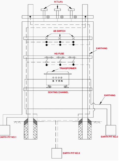
Figure 14 – Earthing of Distribution Transformer Structure